
Furnace Atmosphere Analyzers for Reductive Atmosphere Furnaces (CP Meters)
CP Meters
Features
- Ideal for atmosphere control based on carbon potential (CP) values
- A control sensor featuring long operating life, fast response, and stable readings
Usage
- Endothermic gas generators, continuous furnaces, and batch furnaces for carburizing processes
- Quenching furnaces
- Annealing furnaces
Specifications
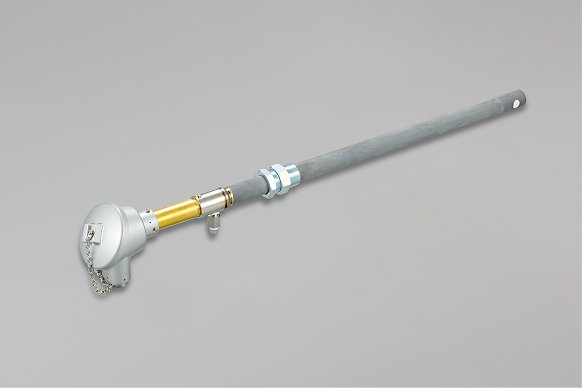
| Model | CP-D/CP-DR Probe Transmitter |
|---|---|
| Measuring Principle | Zirconia type concentration cell method |
| Reference Air Flow Rate | 30–50 cc/min |
| Burnout Air Flow Rate | 2–5 L/min |
| Operating Temperature (Furnace Temperature) |
800–960 °C |
| Terminal Ambient Temperature | −10 to 120 °C |
| Measuring Range | 1 to 10-25 O2 atm (up to the austenitic region) |
| Model | CPM Arithmetic Unit | |
|---|---|---|
| Input Signal | O2 Sensor Input | 1 point, DC −100 to 1,500 mV |
| TC Input | 1 point, Type R or K (selectable via system data) | |
| CO Meter Input | 1 point, DC 4–20 mA or DC 0–1 V (isolated signal, selectable via system data) | |
| Sensor Check | 1 point each, voltage-free contact signal, Contact rating: DC 12 V, 2 mA | |
| CO Meter Input Availability | ||
| Output Display Hold | ||
| Output Signal | Analog Output |
2 points, DC 4–20 mA (load resistance ≤400 Ω) No. 1: CP calculation output No. 2: Temperature, CO, CO2, or O2 sensor input (selectable via system data) |
| Alarm Output |
2 points Contact rating: Resistive load: AC 110 V, 0.5 A / DC 24 V, 1 A Inductive load: AC 110 V, 0.2 A / DC 24 V, 0.3 A |
|
| Power Supply | AC 100–240 V, 50/60 Hz, approx. 15–20 VA | |
| Weight | Approx. 580 g | |
| Ambient Temperature | −10 to 50 °C | |
| Ambient Humidity | 10–90% RH (non-condensing) | |
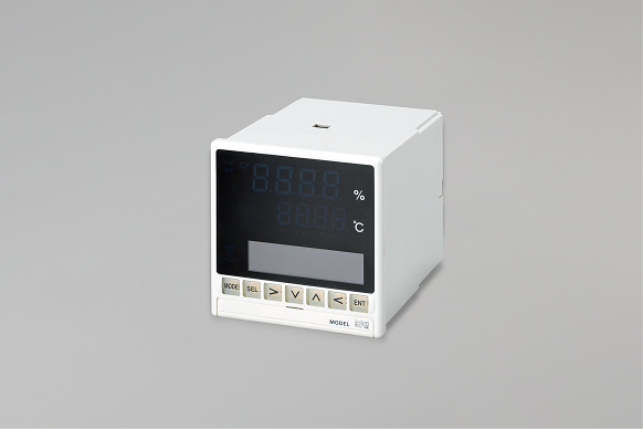
| Model | CPC-D Indicating Controller |
|---|---|
| Measuring Range | 28 thermocouple types, 6 DC voltage types, 1 DC current type, 14 RTD types |
| Temperature Unit | °C, K |
| Accuracy Rating | ±0.1% of measuring range ±1 digit |
| Input Sampling Cycle | Approx. 0.1 seconds |
| Input Impedance |
Thermocouple: ≥1 MΩ DC voltage: ≥1 MΩ DC current: Approx. 250 Ω |
| Allowable Signal Source Resistance |
Thermocouple: ≤100 Ω DC voltage (mV): ≤100 Ω DC voltage (V): ≤300 Ω |
| Maximum Allowable Input |
Thermocouple: ≤±20 V DC voltage: ≤±20 V DC current: ≤±30 mA, ≤±7.5 V RTD: ≤500 Ω, ≤±5 V |
| Current Output Type |
Output signal: 4–20 mA Load resistance: ≤750 Ω |
| Voltage Output Type |
Output signal: 0–10 V Output impedance: Approx. 10 Ω Load resistance: ≥50 kΩ |
| Number of Alarm Points | 4 points |
| Output Signal | Relay output signal (normally open contact) |
| Power Supply | AC 100–240 V, 50/60 Hz, approx. 15–20 VA |
| Mounting Method | Panel mounting |
| External Dimensions |
96 (H) × 96 (W) × 127 (D) (Depth from panel surface: 120) |
| Weight | Approx. 450 g |
| Ambient Temperature | −10 to 50 °C |
| Ambient Humidity | 10–90% RH (non-condensing) |
Resources
Instruction Manuals
-
CP-D (R)
-
CPM
-
CPC-D
Product Inquiries
Please contact us via the link below for any questions about our Measuring Instrument Products.
