- HOME
- > Measuring Instrument Products Top
- > Zirconia Type Gas Oxygen Analyzers (O2 Meters)
- > TF-II, TF-III, TF-IV
TF-II
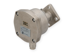
Transmitter Model TF-II
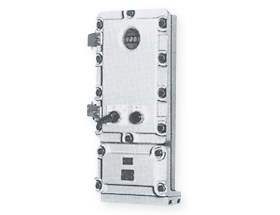
Receiver Model TF-IIM
- Flame-proof structure certified by passing the type test
- Applicable to combustion exhaust gas under extreme conditions, such as high-temperature exhaust gas and exhaust gas from boilers
- No need of standards gas or reference air (air 1-point calibration)
Use
- Combustion control for industrial heating furnaces for petroleum refinery, petrochemistry and city gas making
- Combustion control of atmosphere gas
Specifications
| Model | Transmitter Model TF-II |
|---|---|
| Explosion-proof structure | d2G4 type test pass No. 44241 |
| Measurement principle | Zirconia 2-cell pump form |
| Material | Transmitter: SCS13 Probe: SUS310S/Inconel Flange: SUS304 |
| Weight | Transmitter: Approx. 11kg Probe: Approx. 10kg |
| Product | Receiver Model TF-IIM |
|---|---|
| Measurement range | 0 – 5/10/ 25vol% O2 For remote changeover range: Selection of 2 ranges out of these 3 ranges |
| Output | 4 – 20mADC Non-insulation, load resistance: ≦300Ω |
| Precision | Reproducibility: ≦±1.0%FS, Linearity: ≦±2.0%FS, Drift: ≦±2.0%FS/week (There should be one or more calibration points within the calibration range.) |
| Response time | ≦15 sec: 90% response at calibration gas changeover |
| Warming-up time | Approx. 3 min |
| Calibration | One-push manual calibration with span gas 1-point Calibration gas flow rate: 1 – 2L/min |
| Automatic diagnosis function | Receiver error, sensor error, calibration error |
| Contact output | 2 points: Open collector output (Receiver error, sensor error) 1-point for remote range changeover (Receiver error and sensor error: OR output) |
| Output value hold function | Holds output signal to 0% or last output value, whichever selected. |
| Explosion-proof grade | d2G4 type test pass No. 45930 |
| Utility | Power: 85 – 264VAC, 60/60Hz, Approx. 50W Steam: 0.1 – 0.4MPaG to be used for probe steam jacket |
TF-III
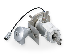
Transmitter Model TF-III
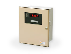
Receiver Model DTF-101
- Applicable to combustion exhaust gas under extreme conditions, such as high-temperature exhaust gas and exhaust gas from boilers
- No need of standards gas or reference air (air 1-point calibration)
Use
TF-III
- Combustion monitoring and control for heating furnaces, holding furnaces, air-heating furnaces
- Combustion monitoring and control of boilers
TF-IIIG
- Combustion monitoring and control for gas melting furnaces
Specifications
| Model | TF-III | TF-IIIG | ||
|---|---|---|---|---|
| (For boilers) | (For steel and iron) | |||
| Measurement principle | Zirconia 2-cell form | |||
| Sampling method | Direct-connection to furnace wall method / Ejector suction method | |||
| Measurement coverage | 0 – 5 / 0 – 10 / 0 – 25%O2 | |||
| Precision | Reproducibility | ±0.5%FS (0 – 10 / – 25% range), ±1%FS (0 – 5% range) | ||
| Linearity | ± 1%FS (0 – 10 / – 25% range), ±2%FS (0 – 5% range) | |||
| Output | 4 – 20mADC, 1 – 5VDC Non-insulated output, load resistance, voltage output: ≧10kΩ, current output: ≦600Ω |
|||
| Response time | 10 sec (90% response at calibration gas changeover) | |||
| Calibration | Automatic (1-point/1-range calibration by air) | |||
| Warming-up time | Sensor: 3 min, Heater: 30 min | |||
| Power source | 100VAC±10%, 50/60Hz, 300VA | 100VAC±10%, 50/60Hz, 500VA | ||
| Air source | Equivalent to instrumentation air Pressure: 0.4 – 0.7MPaG 1L/min at calibration 3 - 12L/min when ejector air is used |
Equivalent to instrumentation air Pressure: 0.4 – 0.7MPaG 1L/min at calibration 10 – 20L/min at purge 3 - 12L/min when ejector air is used |
||
| Measurement gas conditions * |
Temperature | ≦700°C | ≦1,350°C | ≦1,500°C |
| Dust content | ≦100mg/Nm3 | ≦500mg/Nm3 | ||
| Flow rate | 0 – 20m/sec | 0 – 10m/sec | ||
| Pressure | ±5kPa | |||
| H2O | ≦20% | |||
| SOx | ≦2,000ppm | |||
| NOx | ≦500ppm | |||
| Others | No special gas | |||
| External dimensions | Transmitter unit | 155(W)×200(H)×265(D) Excluding projection |
155(W)×200(H)×350(D) Excluding projection |
|
| Receiver unit | 400(W)×700(H)×260(D) | |||
| Mounting flange | JIS5K65AFF | |||
| Transmitter mounting direction | Horizontal or vertically downward | Horizontal (up to 5°downward) | ||
| Weight | Transmitter unit: 4kg, Probe (L = 1,000mm): 2.2kg | |||
* For other conditions , consult with us.
TF-IV
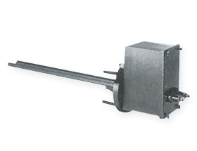
Transmitter Model TF-IV

Receiver Model DTF-101
- Applicable to combustion exhaust gas under extreme conditions, such as high-temperature exhaust gas and exhaust gas from boilers
- No need of standards gas or reference air (air 1-point calibration)
Use
- Monitoring and control of combustion at refuse and sludge incinerator outlets
- Monitoring and control of combustion at melting furnace outlets
Specifications
| Model | TF-IV | |
|---|---|---|
| Measurement principle | Zirconia 2-cell form | |
| Sampling method | Direct-connection to furnace wall method / Differential pressure suction method | |
| Measurement range | 0 – 10 / 0 – 25%O2 | |
| Precision | Linearity | Within ±1% |
| Reproducibility | Within ±0.5% | |
| Output | 4 – 20mA, Isolate output, Load resistance: ≦500Ω | |
| Response time | 10 sec (90% response at calibration gas changeover) | |
| Calibration | 1-point automatic calibration by air | |
| Probe purge | Automatic purge (with indicated hold) | |
| Warming-up time | Sensor: 3 min, Heater: 30 min | |
| Power source | 100VAC±10%, 50/60Hz, 500VA | |
| Air source | Equivalent to instrumentation air Pressure: 0.4 – 0.7MPaG 3L/min at calibration 0.5Nm3/min at purge |
|
| Measurement gas conditions* | Temperature | ≦900°C |
| Dust content | ≦30mg/Nm3 | |
| Flow rate | 5 – 20m/sec | |
| Pressure | ±5kPa | |
| H2O | ≦40% (No oversaturation) | |
| SOx | ≦400ppm | |
| NOx | ≦500ppm | |
| HCl | ≦1,000ppm | |
External dimensions |
Transmitter unit | 188(W)×207(H)×165(D) Excluding projection |
| Mounting flange | JIS10K65AFF | |
| Transmitter mounting direction | Horizontal or vertically downward | |
| Weight | Transmitter unit: 8.3kg, Probe (L = 1,000mm): 2.4kg | |
* For other conditions , consult with us.
- HOME
- > Measuring Instrument Products Top
- > Zirconia Type Gas Oxygen Analyzers (O2 Meters)
- > TF-II, TF-III, TF-IV


